Paw Build Guide
Links
- GeekHack GB thread
- Group Buy page
- Postmortem (will be available once all units have shipped)
PCB Disclaimer
Due to an oversight by the PCB manufacturer, the RGB LEDs are non-functioning. However, this can be fixed with a reflow of the PCB using specialized tools. Please see the Reflowing PCB section below.
Connectivity Notice
If you are having trouble connecting your Paw to your device (e.g. it's not showing up at all, or it's not showing up as a Paw) please flash the firmware provided below.
ZMK Firmware - Paw Fixed Identifier
Assembly
Disassembly is largely the reverse of assembly.
NB: It is recommended that you flash the PCB with your preferred layout before installing it in the case as the reset button cannot be accessed without disassembling the case
Please be careful assembling the case. Overtightening (tightening past the point of feeling pressure against the screwdriver) can cause the threads to strip and damage the case.
- If you removed the weight, first fasten the weight with the two M2 x 3mm screws to the bottom case. Be careful not to overtighten.
- Install switches into the plate, and then solder (or press into hotswap sockets) them to the PCB.
- Fasten the plate with the four M2 x 4mm screws to the top case. Be careful not to overtighten.
- If you are using a battery, plug the battery into the PCB.
- To join the top and bottom cases, place the battery into the bottom cavity and then angle the USB port down slightly to fit into the slot for the USB port.
- Align the top and bottom cases and then fasten the bottom case with the four M2 x 16mm screws to the top case. Be careful not to overtighten.
Flashing
ZMK (Official support)
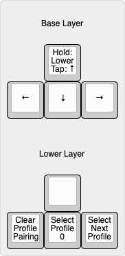
The PCBs come preflashed running ZMK with a simple arrow key layout:
To build and flash your own layout you can follow the setup guide over at ZMK.
Once you have successfully generated a user configuration follow these steps to flash your new firmware:
- Download the firmware UF2 file.
- Connect your Paw to a computer.
- Reset your Paw by quickly double tapping the reset button on the PCB, or by pressing a reset keycode (if programmed).
- A USB storage device should show up in your file explorer, copy the firmware UF2 file to the USB storage device.
- The USB storage device should automatically disappear, once this happens you may safely unplug your Paw (if desired) and use the new firmware.
QMK (Unofficial support)
Due to licensing conflicts between QMK and the Nordic SDK (the manufacturer of the MCU used) we cannot distribute pre-built QMK binaries. Compiling the firmware from source yourself falls into a legal gray area, therefore we do maintain a QMK repository if you wish to do so.
That repository can be found here: AeternusCo/qmk_paw
Instructions for building this firmware can be found here: nrfmicro/wiki
All instructions should be the same except you should be cloning the AeternusCo/qmk_paw repository, and the make command is: make paw_ble:default
Bluetooth Pairing
Disclaimer: There are many factors that determine Bluetooth connectivity performance and distance. While all PCBs have been tested to ensure a baseline of functionality, individual environments can greatly alter real world performance.
- In order to pair the Paw with a device you must first ensure you are on an empty pairing profile.
- If you have not paired the device with anything before it should show up automatically.
- If it does not show up immediately, try selecting profile 0 (Hold ↑, then press ↓) and then clearing the profile (Hold ↑, then press ←).
- If the device still fails to pair, please ensure you are running the latest version of the Paw ZMK firmware.
- If the device still fails to pair, please ensure that there are minimal obstructions between the host device and the Paw.
Reflowing PCB
Video: Coming Soon
In order to fix the RGB LEDs you will have to reflow the MCU module on the PCB and apply some more solder to the underside pads.
NB: This cannot be accomplished using just a soldering iron. You will either need a preheating station or a hot air station. This should only be attempted by skilled hobbyists who feel comfortable using soldering equipment to repair PCBs.
- Heat up the MCU module until you can safely remove it from the PCB.
- Let the PCB cool down, then apply flux and solder to the MCU pads on the PCB (including the underside pads).
- Let the MCU module cool down, then apply flux and solder to the pads on the MCU module itself.
- Heat up the PCB until the MCU pad solder is molten, then heat up the MCU module slightly.
- Place the MCU module on the PCB and ensure all pads feel connected.
- Let PCB and MCU modules cool before testing.
- If RGB LEDs still do not turn on:
- Ensure you are using the default Paw firmware.
- Repeat the above reflow steps.
- Confirm that the reflow attempt did not damage the PCB, the MCU module, or the LEDs.
Contact
Still need more help? Contact us at [email protected]